Table of Contents
MSP430: Common Communication Types
SPI (Serial Peripheral Interface)
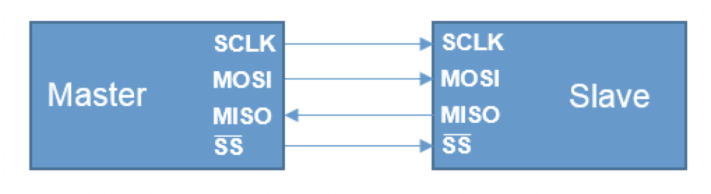
- SCLK – Main clock synchronizing SPI on both devices. Generated by the Master to all the slaves
- MOSI – Master Output and Slave Input in which data is sent from the master to the slave on each clock edge
- MISO – Master Input and Slave Output in which data is sent from the slave to the master on each clock edge
- SS – Slave select, often called CS (Chip Select) or CSn. This line selects the current active slave. It could be Active Low or Active high (refer to the slave datasheet)
SPI Modes- Phase (PH) and Polarity (POL) bits
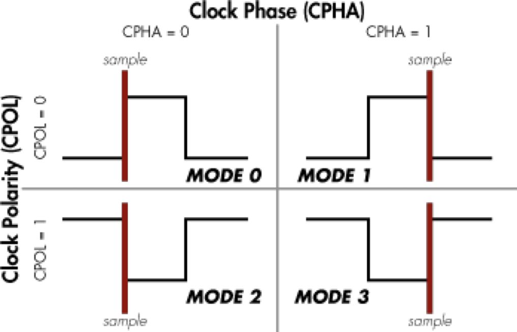
- CPHA/CKPH = 0, Read on the leading edge of each clock pulse. Written on the trailing edge of each clock pulse.
- CPHA/ CKPH = 1 , Written on the leading edge of each clock pulse. Read on the trailing edge of each clock pulse.
- CPOL/CKPL = 0 Clock idles low between transfers.
- CPOL/CKPL = 1 Clock idles High between transfers.
A combination of phase and polarity produces 4 standard modes for the clock in SPI:
| Mode | CPOL/CKPL | CPHA/CKPH |
|---|---|---|
| 0 | 0 | 0 |
| 1 | 0 | 1 |
| 2 | 1 | 0 |
| 3 | 1 | 1 |
It is important that the right phase and polarity are selected so that the slave and master both capture the bit at the correct clock transition.
SPI Communication
- Select the Universal Serial Communication Interface (USCI) modules (USCI_A and USCI _B) or the universal Serial Interface (USI). Some devices have more than one USCI in which called USCI_A0, USCI_A1 and so on.
- Configure the 3 Pins (Clock, MOSI, SOMI) for SPI by configuring PxSEL0 and PxSEL1 to select the SPI function for those pins. (refer to the datasheet of your microcontroller to knew what value you should assign for each register).
Example using UCB0 module for MSp430Fr5969
P1SEL1 |= BIT6;  // P1.6-> UCB0SIMO
P1SEL1 |= BIT7 ; //P1.7-> UCB0SOMI
P2SEL1 |= BIT2 ; //P2.2-> UCB0CLK
* Set up the CS pin as output.
* Set up the Clock speed and mode that match the salve speed and mode. (refer to the slave’s datasheet)
UART (Universal Asynchronous Receiver-Transmitter)
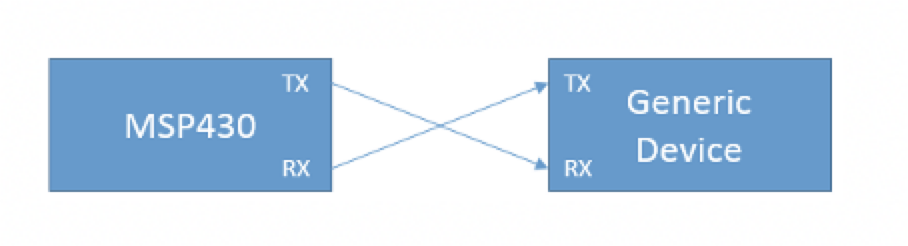
- UART transmits bits sequentially by pulling the UART line low for a fixed amount of time determined by the baud rate. T
- The UART line when idle is high at the I/O level, 3.3V or whatever the VCC of the MSP430 is set.
UART Configuration
- Refer to the datasheet to select the available module for UART.
- Configure the 2 Pins (tx and rx) for UART by configuring PxSEL0 and PxSEL1 to select the UART function for those pins. (refer to the datasheet of your microcontroller to knew what value you should assign for each register).
example using UCA0 module for MSP430FR5994
Config pins for UART operation P2.0 → UCA0TXD , P2.1→ UCA0RXD
P2SEL0 &= ~(BIT0 | BIT1);
P2SEL1 |= (BIT0 | BIT1);
- Set the baud rate.
Baud Rate Configuration
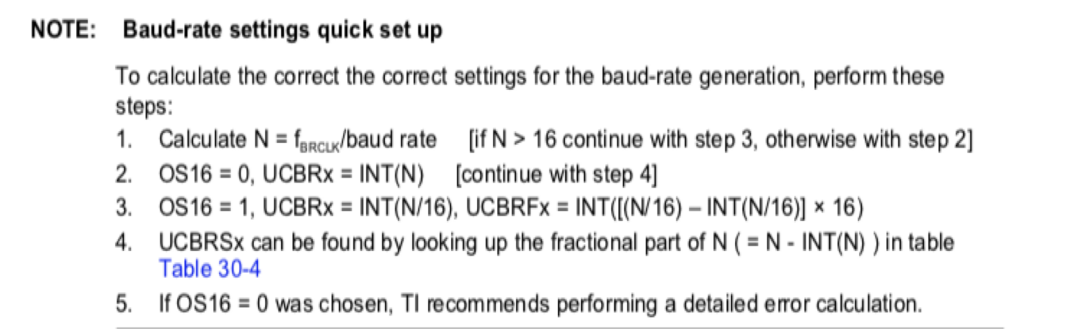
Clock source 8 MHz and desired baud rate is 9600.
Step1: N = 8000000/9600 > 16
Step3: UCBRx = int (N/16) = 52 , OS16 = 1,
UCBRFx = int( ( (N/16) – INT(N/16) ) × 16) = 1
Step4: UCBRSx = 0x49 (by looking up the fractional part of N ( = N - INT(N) = 0.333333)
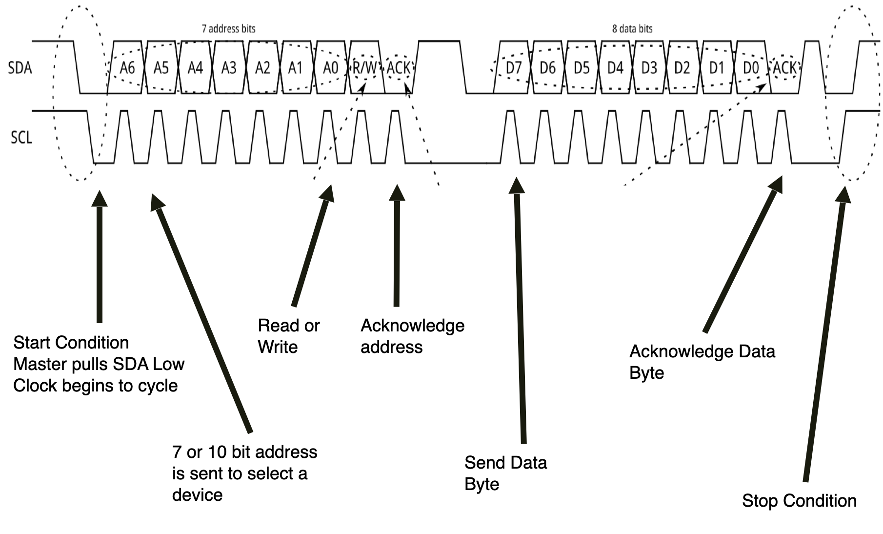
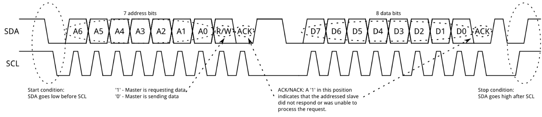
I2C (Inter-Integrated Circuit)
The I2C lives on UCBO on a MSP430 board.
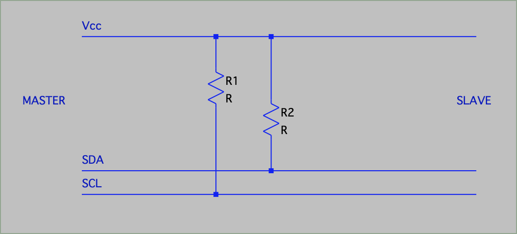
- SDA: Data (default pin 1.6)
- SCL: Clock (default pin 1.7)
Pull Low to send information.
I2C Specifications
- Speed: 100 kbits/second - 3.4 Mbits/second
- Power: Bus draws power when SDA/SCL pulled low
- Vcc = 3.3V, Pullups = 4.7kΩ ∴ 0.7mA*2 = 1.4mA
- Larger resistors → Lower current draw
- Distance: I2C is limited by distance and the capacitance between SDA & SCL
- Designed for simple communication over a short distance
Arbitration
Using clock stretching, the bus can be easily arbitrated: this stalls the bus by holding SCL low. This can be used to allow multiple nodes to be aware of when the bus is in use, or allow a device to stall the bus if more time is needed to handle data.
Setup
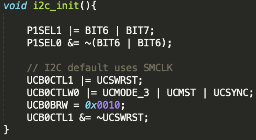
- UCSWRST: Put USCI_B in reset state
- UCMODE_3: I2C Mode
- UCMST: Master Mode
- UCSYNC: Syncronous mode
- UCB0BRW: Baud rate SMCLK / 0x<UCB0BRW>
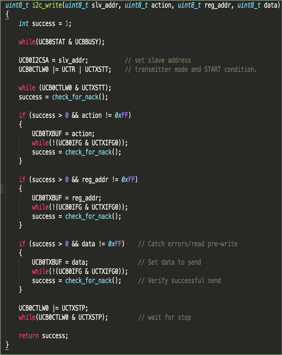
Sending data
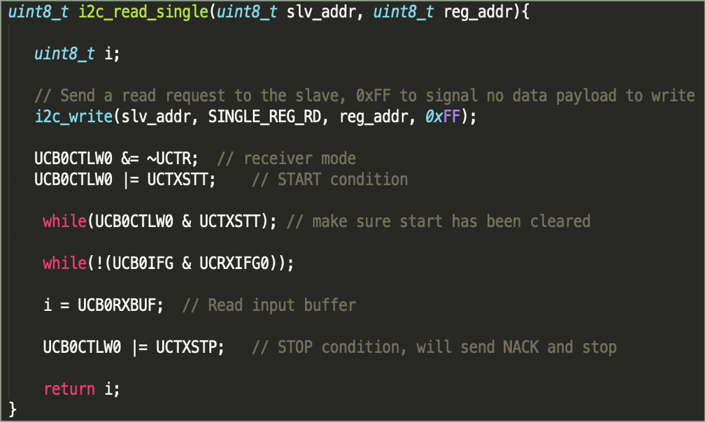
Reading data
References and Further Reading
- Msp430FR5994 User’s guide http://www.ti.com/lit/ug/slau367o/slau367o.pdf
- Evaluation of Power Efficiency for Digital Serial Interfaces of Microcontrollers https://ieeexplore.ieee.org/stamp/stamp.jsp?tp=&arnumber=6208716